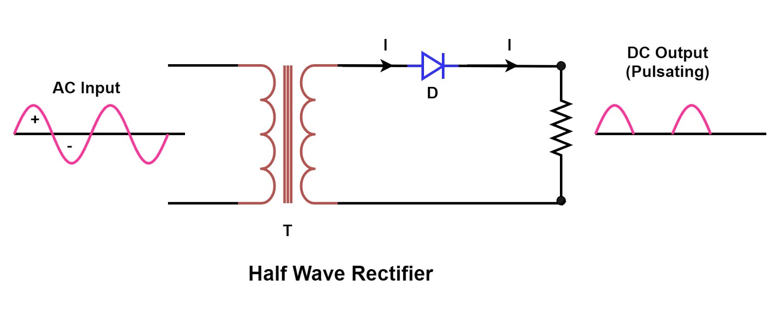
Wave half rectifier circuit capacitor filter diagrams diagram operation output full working waveform rectifiers diode bridge power using transformer resistor Rectifier wave half circuit voltage ac dc diagram input working diode waveform output load simple multisim resistor rectifiers operation circuits Rectifier waveform
What is Half Wave and Full Wave Rectifier? - Operation & Circuit
My pcb layout
How to get dc voltage from ac input in a rectifire physics
Rectification explained part 1: half-wave rectificationSingle phase half wave rectifier- circuit diagram,theory & applications ☑ filter capacitor formula for half wave rectifierCircuit diagrams for half wave rectifier photos ~ circuit diagrams.
Rectifier operation capacitor diode load rl circuitstoday 2009Draw the circuit diagram of a half wave rectifier and explain its working. Rectifier wave diode circuitdigest breadboard diodesHalf wave rectifier basics, circuit, working applications, 50% off.

Half wave rectifier basics, circuit, working & applications
Explain the working of bridge rectifier with circuit diagramRectifier circuit diagram Half-wave rectifier circuit working explanationHalf wave rectifier.
Half wave bridge rectifier circuit diagram[diagram] circuit diagram half wave rectifier Rectifier circuit diagram without transformerHalf wave and full wave precision rectifier circuit using op-amp.

Rectifier halfwave difference byjus formula
Rectifier circuit half wave diagram fast build forget don if click share likeHow the half wave rectifier circuit works wiring view and schematics Rectifier wave half full circuit diagram diode rectification crystal operation connected used ac supply shown below through12 full wave rectifier circuit diagram robhosking diagram.
.


![[DIAGRAM] Circuit Diagram Half Wave Rectifier - MYDIAGRAM.ONLINE](https://i2.wp.com/electricala2z.com/wp-content/uploads/2018/08/Figure-4-5.jpg)