Half wave bridge rectifier circuit diagram Half wave & full wave rectifier: working principle, circuit diagram Half wave bridge rectifier circuit diagram
Describe the Half Wave Rectifier Using a Diode
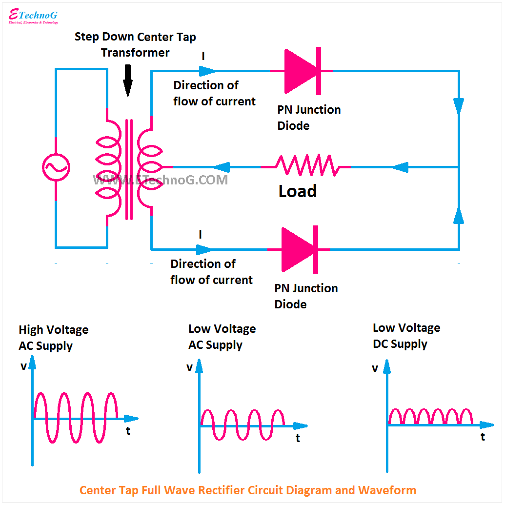
Full wave rectifier bridge circuit diagram
Rectifier circuit diagram without transformer
Full wave bridge rectifier circuit diagramBridge rectifier wiring diagram Full wave bridge rectifier schematicSimple bridge rectifier circuit.
Half wave bridge rectifier circuit diagramHalf wave bridge rectifier circuit diagram Full wave rectification diagramFull wave bridge rectifier circuit diagram.
![Half Wave Bridge Rectifier Circuit Diagram](https://i2.wp.com/www.electroduino.com/wp-content/uploads/2021/04/What-is-Half-Wave-Rectifier-Working-Principle-Circuit-Diagram-Waveforms.jpg)
[diagram] h bridge circuit diagram
Bridge rectifier diagram discount compare, save 44%How the half wave rectifier circuit works wiring view and schematics Half wave bridge rectifier diagramDescribe the half wave rectifier using a diode.
.
![Half Wave Bridge Rectifier Circuit Diagram](https://i2.wp.com/how2electronics.com/wp-content/uploads/2022/09/Half-Wave-Rectifier.jpg)
![Half Wave Bridge Rectifier Circuit Diagram](https://i2.wp.com/cdn1.byjus.com/wp-content/uploads/2021/01/half-wave-rectification.png)
![Full Wave Bridge Rectifier Circuit Diagram](https://1.bp.blogspot.com/-ph3wPcxTMhg/YO60L9F14dI/AAAAAAAABM0/svLo3j9BnrEtn4_4Ldv94ZgxqVJXvAE7ACLcBGAsYHQ/s1035/Center+Tap+Full+Wave+Rectifier+Circuit+Diagram.png)
![Rectifier Circuit Diagram Without Transformer - Uploadist](https://1.bp.blogspot.com/-uzWX38U8Hjs/YO60pnoF8UI/AAAAAAAABM8/otQyNJpK8PIUk9vmeOwTroo0cMf9xL06ACLcBGAsYHQ/s16000/Full%2BWave%2BBridge%2BRectifier%2BCircuit%2BDiagram.png)
![Describe the Half Wave Rectifier Using a Diode](https://i.ytimg.com/vi/STLPgPOThoY/maxresdefault.jpg)
![Half Wave Bridge Rectifier Diagram](https://1.bp.blogspot.com/-bTCLeh50vOE/YO6z8d2H3zI/AAAAAAAABMs/w7vO2Gw8nTcJVMMKq1r3cBeyP8caaUywwCLcBGAsYHQ/s16000/Half%2BWave%2BRectifier%2BCircuit%2BDiagram.png)
![full wave rectification diagram - Wiring Diagram and Schematics](https://i2.wp.com/circuitglobe.com/wp-content/uploads/2015/12/HALF-WAVE-AND-FULL-WAVE-RECTIFIER-FIG-1-compressor.jpg)
![Simple Bridge Rectifier Circuit](https://i2.wp.com/circuits-diy.com/wp-content/uploads/2019/12/F-1.jpg)
![How The Half Wave Rectifier Circuit Works Wiring View And Schematics](https://i2.wp.com/blogger.googleusercontent.com/img/b/R29vZ2xl/AVvXsEgevVBtf4LFjqQMvC8pg3EMU54ROvfZp1q76y0iCAvieLX3hhvzo9Vh_sa-Z2mvdYaLQOPCUpKi7fIF_2-aGcLnMXb60syVUnu05UU-OHxK9szRr1AsO3Y5bQOVT1Stwu72ZVQkre9OXNPiKuwFUg2EOyZEiYg_ZAXTjD_IGHmm_wPpKexDOaVeZiY8eA/w1280-h720-rw/During-positive-half-cycles-in-half-wave-rectifier-circuit_Electrothinks.gif)
![Half Wave & Full Wave Rectifier: Working Principle, Circuit Diagram](https://i2.wp.com/electricala2z.com/wp-content/uploads/2018/08/Figure-4-5.jpg)